An MIT Maze for an at-home entertainment system
This projects task was to get familiary with numerically controlled machining. I bought a nice piece of plywood at Home Depot and decided to make a design that hid the wires coming from the speakers and TV in my living room. Of course, it needed an MIT theme.
At the moment of this investigation, I was into mazes for some reason. Likely because I had just come back from a Halloween night at the Queen Mary in Long Beach, CA, that required you to go through 2 out of 7 mazes where people scared you before you made it into one of 3 dance floors of the enormous boat! Mazes seems to really capture the divergent and convergent thinking that goes on at MIT, so this project mixes the two.
For more details and tips on cnc machining, take at look at my documentation page on the fab website of the Center for Bits and Atoms at the MIT Media Lab.

Design
Ratio and Maze Details
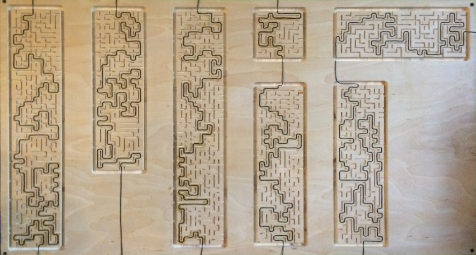
I obtained the MIT logo directly from web.mit.edu, which has a ton of specs on the logo design. More than you can imagine. I had decided on a 2ft by 4ft mount for the entertainment system. It worked well because the MIT logo is almost a 2:1 ratio. I left a 1 inch border margin around the logo, which left the actual logo size at 22 by 33.5 inches.
Each block of the MIT logo was then designed to be a maze. After using inkscape to get the ratios/measurements of each of the blocks, I used mazegenerator.net to generate the appropriate mazes. Mazegenerator.net is great. It is a simple interface that takes the width, height, and starting location of the maze as inputs. It also can export as png or svg, with and without the solution to the maze. But the best part is that it has advanced setting. Oooooooh! I know right?! Maze generator lets you control two specific maze generation algorithm settings, Elitism and River Tendency.
E-value: Controls the elitism tendency of the algorithm. An elitist maze has a short solution relative to the size of the maze. The lower the value, the more elitist the maze R-value: Controls the river tendency of the algorithm. A maze with a high river factor has few but long dead ends. The lower the value, the higher the river factor.
For the mount, I picked a value of 1 for the E-value because I wanted the wires to cover a large portion of the maze. The mount would look silly if it did not abstractly fill in the MIT logo block. As for the R-value, I also picked a value of 1 because I wanted long dead ends. I figured long dead ends would give a cleaner look (fewer walls) and it would also speed up the cutting time. I created all seven mazes using the height, width, a starting point of "top," and using the above mentioned E- and R-values, and exported them all, with solutions, as .svgs.
Inkscape and Rhino
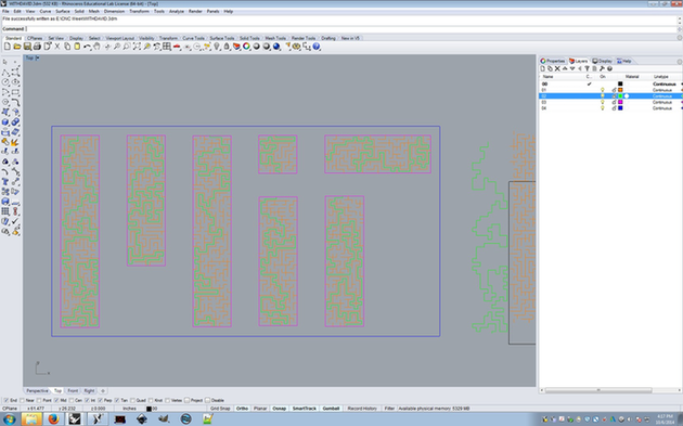
I created the design in Inkscape because of my familiarity with it. It allowed me to resize the mazes, select different components, and edit them so there was a clean transition from one block to another. However, the final layering and edits were done in Rhino. Rhino allowed me to place the entire design at the origin, edit the paths (not the line thickness) of all my lines, and allowed me to group all the walls of the mazes in each block together to minimize the team needed to cut. It was also easy to export in a format compatible with Mastercam, which is what the Onsrud machine likes.
CNC Router: C.R. Onsrud
I ended up buying a smooth finish, 3/4 inch plywood from the Home Depot because I was afraid that the cuts on OSB would not be distinguishable given its dirty look. After importing my Rhino files into Mastercam, I was able to create the tool paths for each part of my mount. I created four tool paths in total. The bit sizes were chosen to leave enough space in between the walls of the maze for a solution path to go through. The depth was chosen based on my wood thickness (which was measured using calipers) and the thickness of my 22 guage speaker wire. Toolpaths were fairly simple to create, and I had a lot of help from David Costanza (Thanks!). Given that I was using a 3/8" bit to cut all the way through a 3/4" piece of plywood, I ended up making it in two passes and slowing down the speed by 25% of that tool in particular.
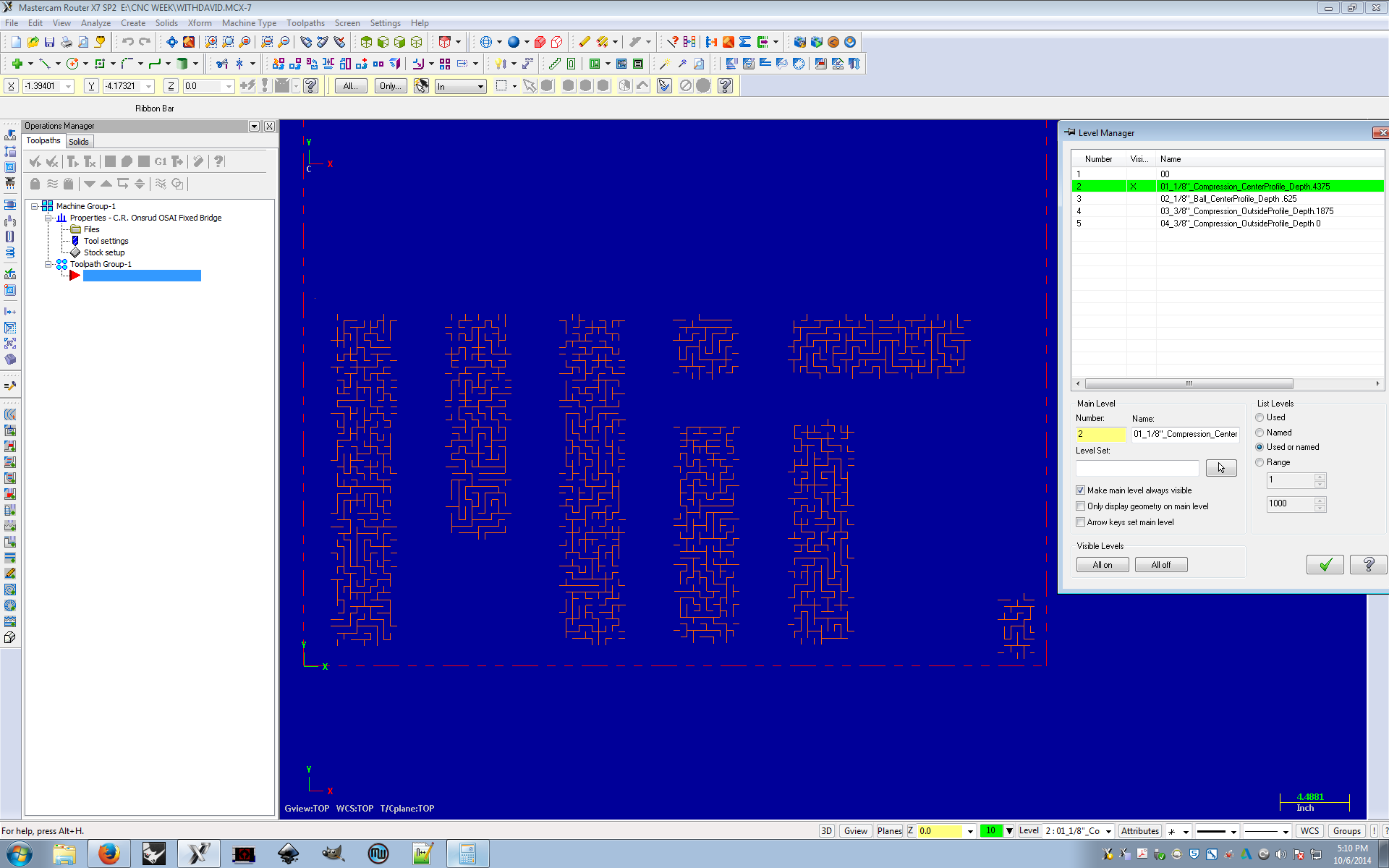
Layer 1 (red) was called "01_1/8"_Compression_CenterProfile_Depth.4375" and was used to create the walls of the maze. Layer 2 (green) was called "02_1/8"_Ball_centerProfile_Depth.625" and was used to create the solution to the maze, the guide for the wires. Layer 3 (magenta) was called "03_3/8"_Compression_OutsideProfile_Depth.1875" and was used to create the MIT logo block outside profiles. Layer 4 (blue) was called "04_3/8"_Compression_OutsideProfile_Depth0" and was used to create the 2ft by 4ft border around the mount.
Also, since I was using a ball end mill, I had to switch out the tool in the Onsrud machine. Costanza told me to switch out tool number two. The was fairly simple. You remove the old bit from the holder, place the new bit to where the holder grabs onto the flat piece of the bit (not the flutes), and tighten using a torque wrench. Onsrud has specs on how hard to tighten the tools. After tightening, you measure the tool (including the holder), and update the value on the Onsrud table in the software.
You then input the files into the Onsrud machine and Voila!
The piece took about 35 minutes to complete. It. Looked. Amazing! There was, however, lots of dust in the crevices of the mount. I used a small shopvac to remove most of the saw dust, but had to switch to an air compressor to remove the small pieces. I also had to sand down the edges. Although I used a compression tool to cut, it didn't leave as smooth of a cut as I wanted.
Installation
The entire display was mounted onto the wall using four screws. I initially wanted to use 3M's double sided tape to hold it up, but it did not hold (and I was not willing to spend $20 for larger pieces. Psh, LeVerde's). Although I used screws for the entire mount, I used nails to maneuver thicker wires around the MIT sign. The nails allowed me to hold the wires taut and make right angles, which, aesthetically, fit better with the right angles of the mazes.
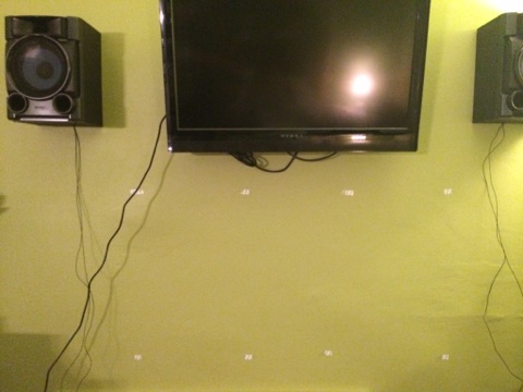
The 22 gauge wires were the only wires that passed through the solution of the design. The thicker wires (power and hdmi cables from tv) were wrapped around the design and held down using nails. The speaker wires were held down on the solution of the maze using Krazy glue.
Krazy glue is Cray
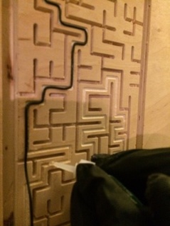
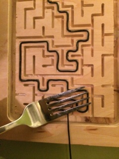
Unless you want to rob a bank and are clostrophobic, in your hands only, and so you cant wear gloves, so you need a way to remove your fingerprints from your fingers, I would wear gloves while working with Krazy glue. It is very sticky. And since it runs, it is very difficult to keep clean. On areas with many turns close together, I ended up using a fork to hold the wires down while the glue set. Usually, however, I just flew by the seat of my pants most of the time, alternating between forks, fingers, and swear words.
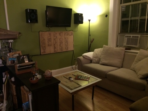
Once all mazes were solved, I routed the wires behind my DirectV receiver, organized the power cable from the tv, looped the antenna cable to the receiver, and held the hdmi cable down. The final design is shown below!


