A Smart Insole
This work was a contract gig for a private investor. With permission, they have allowed me to display this inner workings of this project.
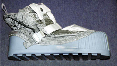
The Smartboot is a boot with sensors on the outside and vibrators on the inside sole that vibrate to provide proprioceptive feedback to a user when specific environmental triggers sensed by the sensors occur. During Extra-Vehicular Activities (EVA), astronauts wear boots that attach to the Canadarm, a multi axis robotic arm. However, during the 6 terrestrial human missions (Apollo), astronauts actually walked on the Moon! I know right?!?!?! They walked on the Moon!
Anyways, astronauts actually had difficulty walking because of the reduced feedback they had on their feet (and because the suits were not very mobile). The best/funniest example can be seen in the Astronaut Falling on the Moon Video. Walking on the moon with these boots is similar to walking with ski boots. The restrictive motion and feeling makes it difficult to discern texture, slipperiness, conductivity, temperature, etc. Thus, this astronaut boot will revolutionize the world (and others).
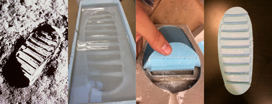
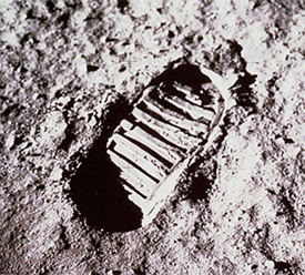
Below is the iconic footprint left by Buzz Aldrin.
For this design, the sensors are placed at specific position on the sole of the boot. Heel and toe inertial sensors measure the motions of the foot during the gait cycle. Temperature and conductivity are measured between the toe part and the heel part of the sole. Strain gauges mounted to the central nubs of the tread, measure shear and traction forces during the ground- phase and are used to indicate slippage. The cameras and light sensors are positioned so they are protected from the heel strike and walking motions. Finally, a piezo-electric device is loaded during every heal strike and determines the hardness of a small soil sample.

Video
Video of 2D and 3D in ONE sketch
Bill of Materials
In addition to a plethora of solder wire, heat sticks, copper braid, heat guns, tweezers, double sided tape, flux, connection pins, and the milling boards, I used hydrostone, oomoo, and Sorta-Clear 37 for aesthetics from Reynolds Advanced Materials in Boston. Vibrators, strain gauges, etc. were off the shelf. The straps that hold the boot are from Economy Hardware in Central Square.
A Modela machine was used to mill out the components. A 3-axis Onsrud CNC machine was used to mill out the soles. I also took advantage of the fume hood when casting components.
The final bill of materials, with cost and purchase location, can be found here. The total cost of the boot with only the current components that are installed is about $70, the most expensive part being the clear silicone. (you can easily find a cheaper urethane, I just thought it looked cool see-through.
Schematic Design Overview
Visualization
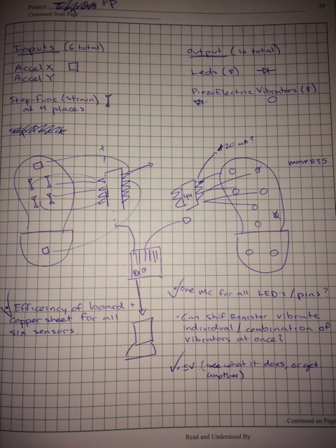
The idea was to split one FTDI cable into its TX and RX wires, one to each board. Each board would then independently parse or output data. The FTDI cable would be the key for visualization of the data, allowing me to use processing to display informations on a laptop screen. The process started like this...
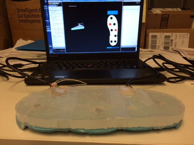
... And ended up, much more mature (and with only accelerometers and vibrators), like this...
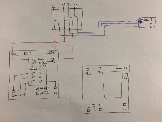
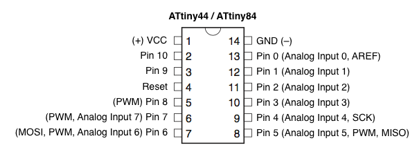
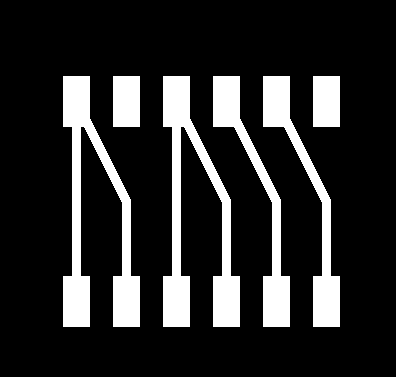
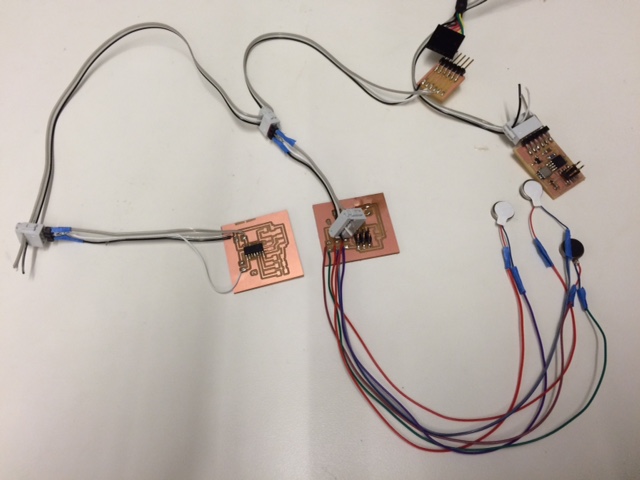
The diagram above shows four boards that need to be created. One board was just a splitter of the FTDI cable. It easily allowed me to move TX and RX lines to the appropriate board, and let all boards share the Gnd and Vcc lines. The right most board just spit out data to the computer about the board orientation using an ATTiny45. The other two boards have an ATTiny44 in each, each controlling 4 vibrators. This was because only 4 of the pins of an ATTiny44 have Pulse Width Modulation (PWM) capabilities, and thus I needed two.
Milling
All the boards were designed in Eagle, exported as pngs, and milled with the Modela machine controlled by an online class fab module (mod.cba.mit.edu). Traces were cut using a 1/64" endmill, and the board outline was cut using a 1/32" endmill. The three board components, if you are so inclined to reproduce this project, are below.
FTDI Splitter - traces - outline. Accelerometer - traces - outline. Vibrators - traces - outline.
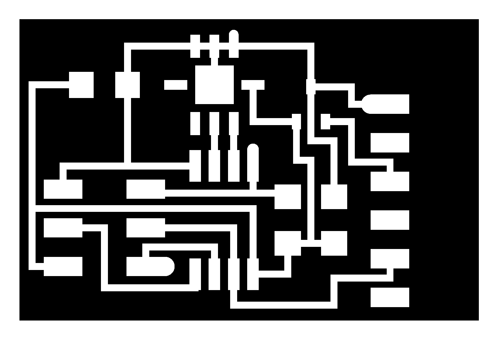
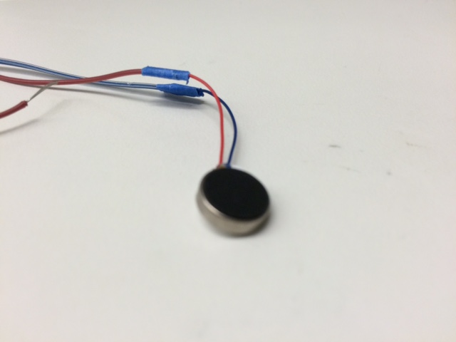
The vibrator board actually just uses resistor traces where the vibrators would connect. I used it because I just needed the space to solder on the pin and gnd leads of the vibrators. In order to allow the vibrators to reach the entirety of the boot, I had to extend the leads of the vibrators by soldering twisting the two ends together, soldering a little bit, and covering with blue tape (couldnt find painter's tape).
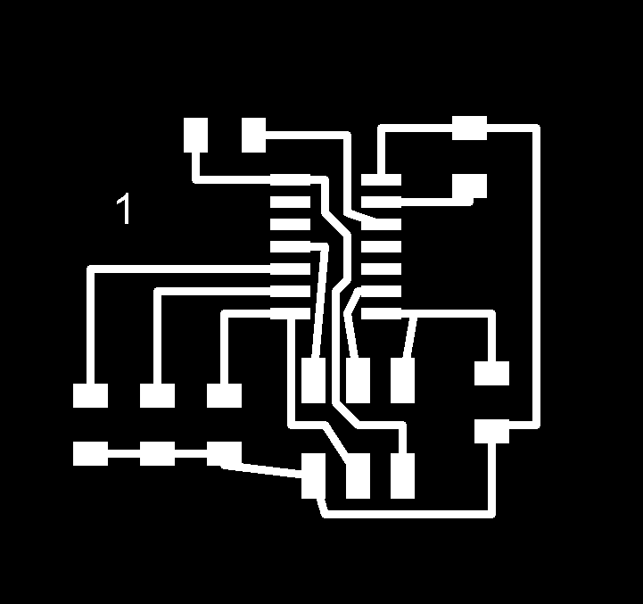
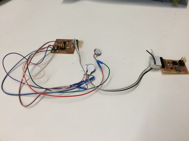
The final configuration models the layout above.
However, this layout did not allow me to communicate with the accelerometer. I checked all components, and I was receiving signals where I needed to, but I could nto find the culprit. So instead, I hard wired the accelerometer board to the vibrator board to make it work in the mean time. The final, final layout is below.
Software
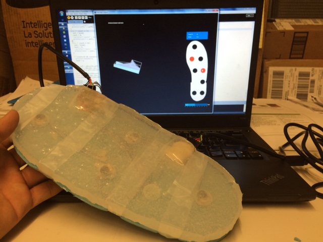
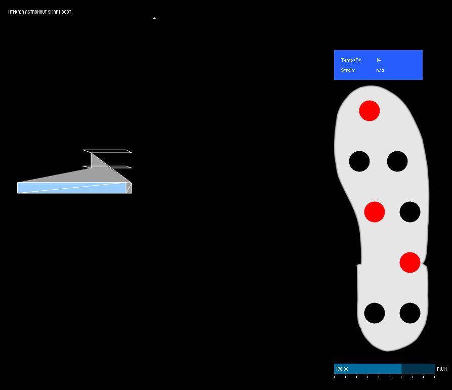
The interface for the smart boot has a 3D boot that rotates with the accelerometer data input, vibrator buttons that produce vibrations of the vibrator button pressed, a PWM slider that states how much to vibrate, and temperature and strain readings that currently are static, but were implemented for when these sensors are integrated.
Processing
Processing was used to created the visual interface. I imported the Serial and ControlP5 libraries. They are pretty standard libraries that allow for serial communication and visual controllers, respectively. Google it. The processing sketch can be found here
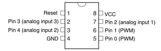
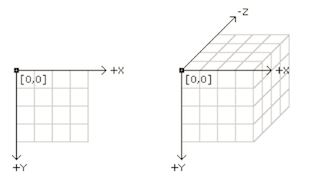
The code instantiates a serial port and reads in byte data from the accelerometer. It continually calculates the max and min values coming in and maps them to -90 to 90 to associated them with angles. The angles then dictate how much to rotate the 3D boot, mimicking the motion of the boot on the screen. The standard processing axes are shown below. Processing is also in charge of serial communication to the vibrators. A second serial port is turned on, and through this port, vibrator data is sent in bytes. The ATTiny44s on the boards read in these bytes and turns on the correct vibrators based on the values. The data communicated is an 8byte array consisting of 0 and 1s. The 1 indicates that a vibrator is turned on, and the index of that value determines which vibrator. For example, [0,0,1,0,1,1,0,0] means that vibrators 3,5, and 6 must be on, and all others off.
Other features that currently do not work are also displayed for when I have time to debug. Ideally, the PWM slider information would also be sent, telling the microcontroller how much the vibrators to vibrate. The temperature and strain values would also update the interface, but this has yet to be implemented.
Arduino
The arduino code was pushed onto to ATTiny44s to control the buttons based on which vibrators were highlighted on the screen. Attiny44s have a 4K byte memory. Including a SoftwareSerial.h library and instantiating a serial port takes up about 75% of the entire memory. Rather than having a Serial Event function that interrupts the while loop, I had a line that checked to see if anything was queued in the serial comm, and to pull out the information if there was something. Also, "switching" took up less memory than if() statements, comments were removed, and arrays for comm were used to take up less memory. The code can be found here.
C
The accelerometers were programmed in C. Avrdude and a fabISP were used to program the board. The code was adapted from Neil's hello.accel board to read serial without using a library, and allowing for various calculations to be done on the micro- controller. Neil's code can be found here.
Casting the Boot
Design and Milling
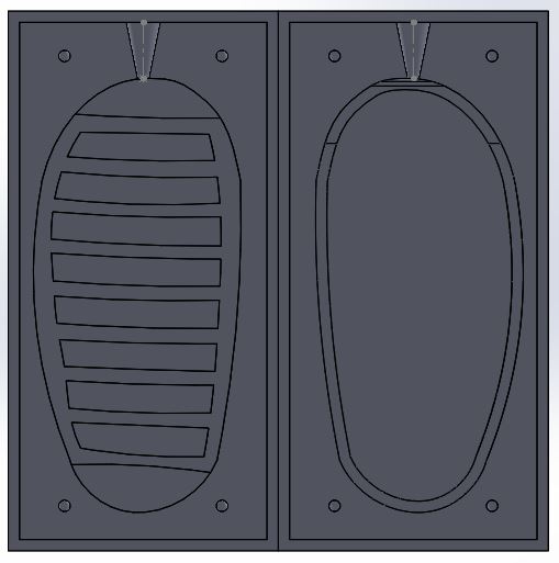
The two pieces (top and bottom) of the boot were made in solidworks. Each of the two pieces had a pour hole, sprices for venting air out, and a basin to hold everything. It was originally going to be a two part mold, but the top part had issues with releasing the Oomoo given the small thickness of the walls. The design was then imported into rhino for layer editing, and from there, it was imported into Mastercam to create toolpaths. The blue foam was milled out by the Onsrud machine.
Molding and Casting
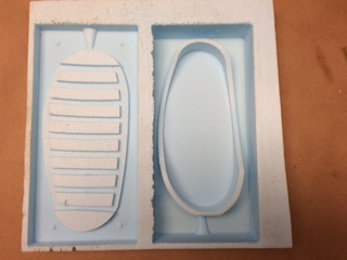
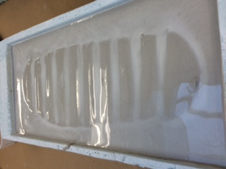
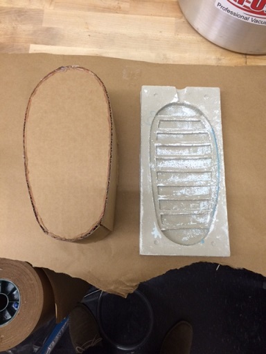
Like always, when blue foam is milled, it comes with frayed pieces. I used a vacuum and shop air to try and clear out most of the loose pieces. I even quickly passed a heat gun to melt a layer of blue foam to help with fraying and sealing. I covered the moled with Gesso, commonly used on painting canvases to create an even layer. It helped seal the blue foam from the hydrostone. I liberally applied mold release spray. Finally, I mixed hydrostone and poured it into my blue mold to create a hard negative mold of the sole. When dry, I used this negative mold to create the sole of my boot using Oomoo (blue silicone). Remember to also add mold release on the negative mold you are casting from!

Clear Top Layer
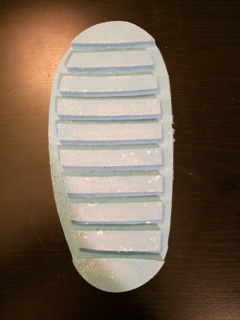
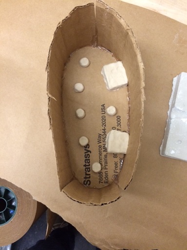
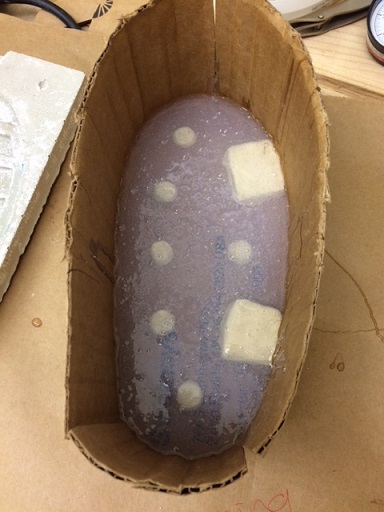
Due in part because the sole was created a couple of weeks before the top clear layer, and due in part because I did not have time to redesign the mold with thin walls, I made a negative mold of what I wanted my top layer to look like out of cardboard and clay. I traced the sole of the boot, cut out the cardboard, and lined the cardboard with walls using hot glue. I then placed pieces of clay where I wanted components (boards, vibrators) to be to create a space for them. I hot glued everything together to create a strong seal, applied mold release, and cast the top of the sole using Sorta-Clear 37.
The final top layer came out pretty good given my McGyver way of creating the mold. The Sorta-Clear peeled easily off the cardboard and clay. By stirring it aggressive while mixing, I was able to get bubbles for a space themed design.
![]()
![]()
![]()
I added the vibrators in their appropriate sections, and use clay to hold them in place higher towards the top of the layer so as to be closest to the foot. I had difficulty holding the boards in place. Hot glue did not work well on the silicone, so I ended up using more clay to create a tighter fit for the boards. I routed the cables to look pretty, placed the sorta-clear sample on top of the blue oomoo sample, and used scotch tape to hold them together (So the clear aspect still holds)
Final Product